©Stephen G James - 76/11 Hollister Lane, Ohauiti, Tauranga Ph: (64) 7 5447177 - Email steve@ontherails.com
Site design and hosting by Get Web Design and Hosting
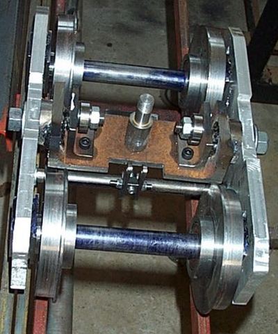
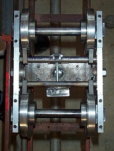
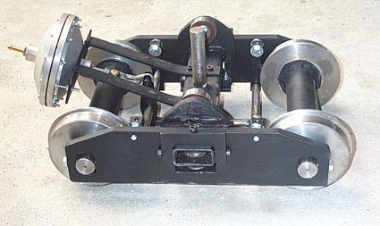
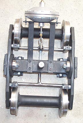
This shows the top and bottom view of the bogie. The side plates are 12 x 65mm aluminium bar with the usual horn slots and sprung axle boxes. The sides are mounted on a centre trunion with a centre pivot allowing the sides to twist independently of each other. The rollers on the trunion are set inside the wheel base. Each wheel has two ball bearings inside the wheel accounting for the large boss on the rear of the wheel. The axle is locked at one side in the axle box. (The other needs to rotate slightly to get the twist.) Brakes are fitted and will be actuated by a bowden cable.With the bogie sitting on the track any wheel can be raised 12-15mm without the others lifting and with no load other than the bogie.
Following considerable discussion on the design of bogies for a 5" ride car and the problems with minimizing tipping on a ground level track I have tried to bring together the ideas with the following results.
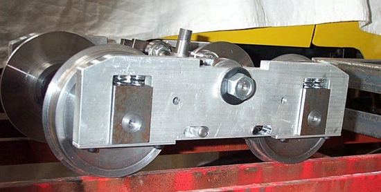
The side view of the bogie shows how the side plates can move independently on the trunion, the axle boxes and the springing
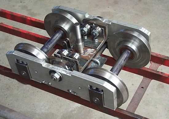
I later modified the bogies by fitting 4 top rollers per bogie to stop the tipping of the trunion on the pivot pin.
Also lengthened the centre pivot pin.
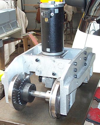
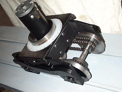
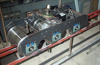
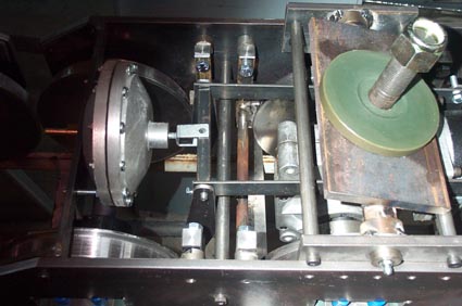
These pictures will give a good idea of ways of getting the power to the wheels in a bogie.
When we completed a Tranz Rail DH Loco 5" gauge using 400w 24v EMD motors mounted vertical and using angle grinder gearboxes for the right angle drive. This has proved very successful and has been used in a commercial operation for some years.
The construction of a Tranz Rail DXR 7.25g is underway. This is a CoCo Diesel Loco a rebuild of the large DX loco. The power bogie shown is almost completed. The vacuum brake system has yet to be fitted and the side detailing. Each bogie is powered by an EMD 24v 40A 4 brush motor and right angle worm drive to the centre wheels which are in turn chain driven to the outer wheels.
Below braking system
Following the article on a 7.25" Straddle Type Passenger Car in the Australian Model Engineering Magazine our club decided to use this design for new ride cars. The bogies however were modified to make construction easier but keeping to the principles of the original design. The new design is shown in the following pictures. We added vacuum brakes, ball bearing rollers on top and used 12mm stock for the side frames.
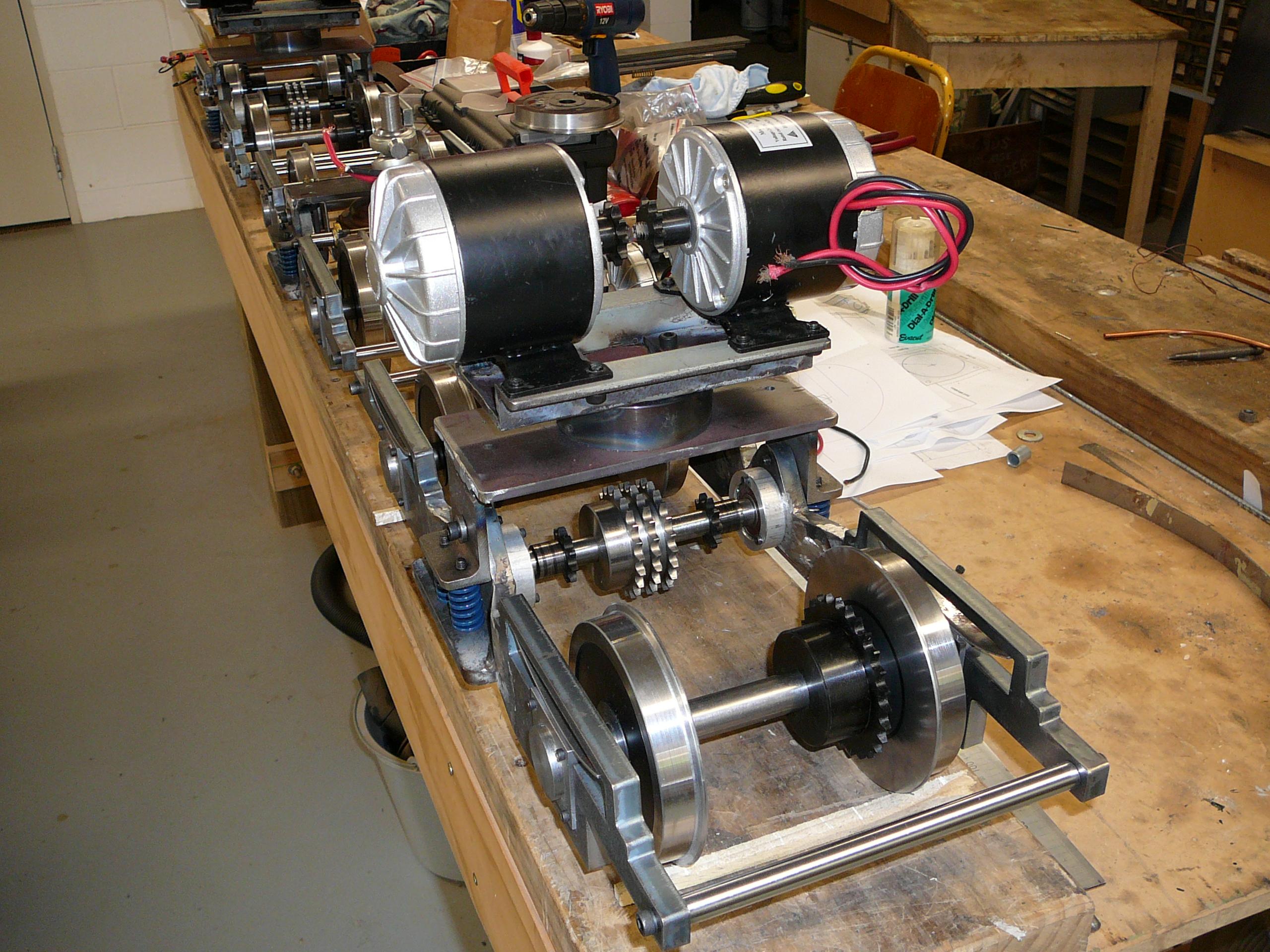
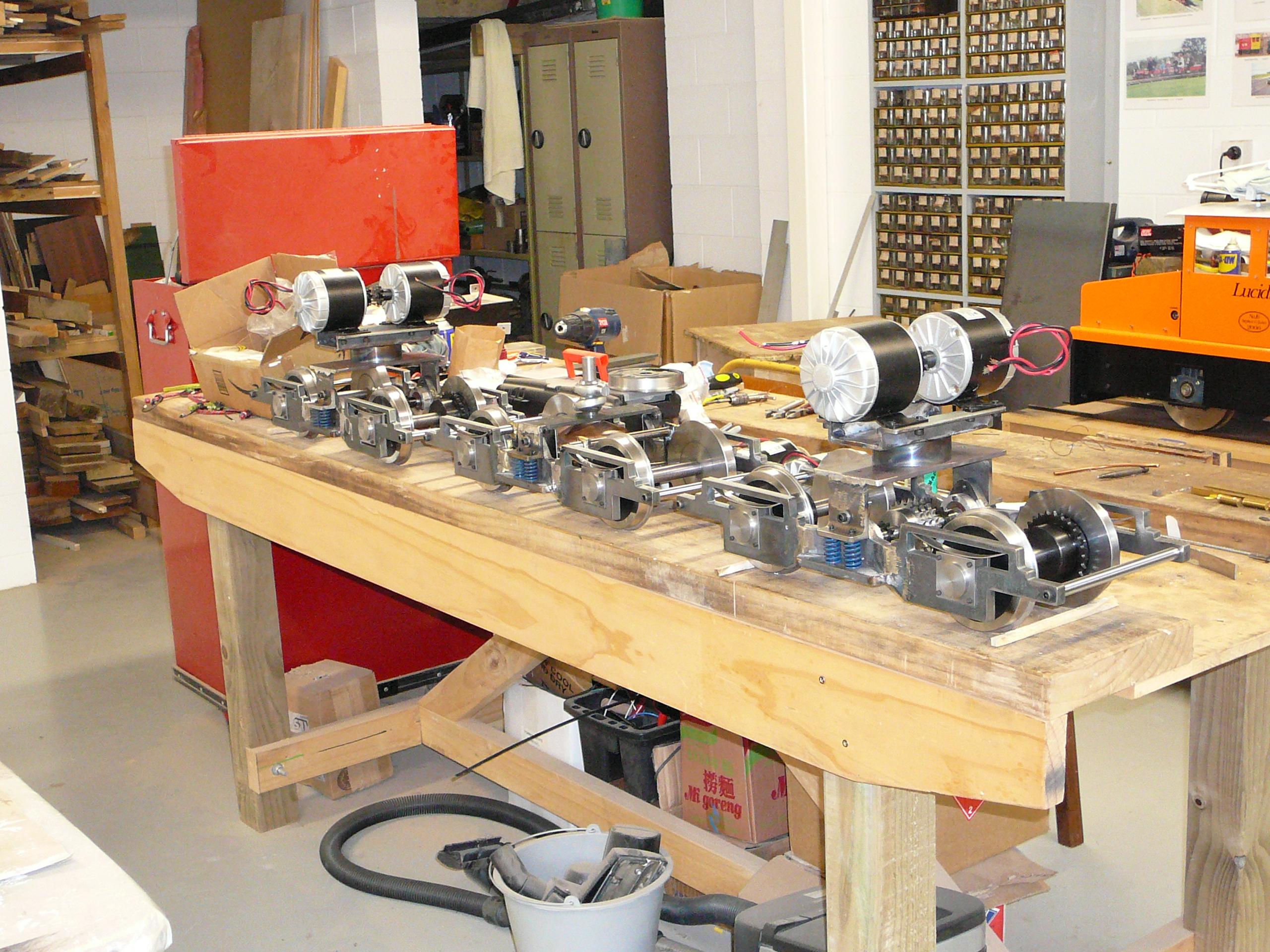
The latest project is an electric articulated locomotive of the EW class. These had 3 BoBo powered bogies with the centre bogie being common to the front and rear units. In 5" gauge the bogies are shown. The two 300 watt motors are mounted above chassis and chain driven through the trunion. The front and rear bogies are identical with the centre common bogie having the train braking system.


