BUILDING THE NZR EW ELECTRIC LOCOMOTIVE 5"g
©Stephen G James - 76/11 Hollister Lane, Ohauiti, Tauranga Ph: (64) 7 5447177 - Email steve@ontherails.com
Site design and hosting by Get Web Design and Hosting
In October 2006 I embarked on building an English Electric NZR "EW" locomotive in 5" Gauge. This was introduced into New Zealand in the 1950's to assist the Wellington electrified rail network ageing fleet of ED class Locomotives. The design was a triple bogie locomotive which was articulated on the centre bogie. The design presented it challenges to the designers and well as a good challenge to building it in 5" gauge.
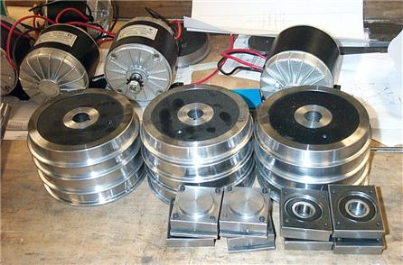
By the end of October the project was well underway. Twelve wheels, axle boxes, 4 motors and sundry bits were accumulated and are shown here awaiting assembly.
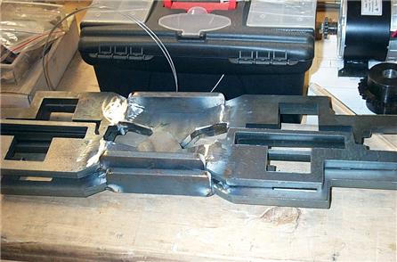
The bogie side plates were laser cut to my specifications from 12 mm mild steel plate. The centre recess for the springs was created by partially cutting the plates then bending into shape by hand before welding to keep the set.
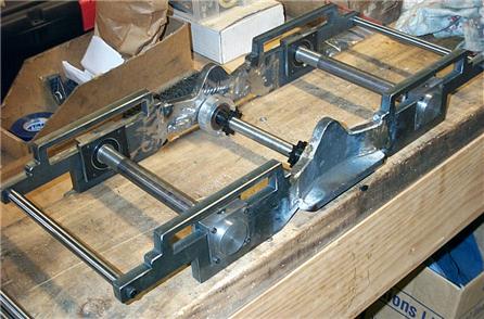
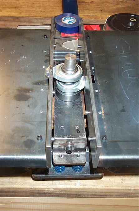
The bogie assembly showing side plates, end spacers axles and lay shaft for the chain reduction gears, Note the long slots above the axle boxes to accommodate the working leaf springs. The springs were made up of 4 leaves of 1mm x 12mm spring steel.
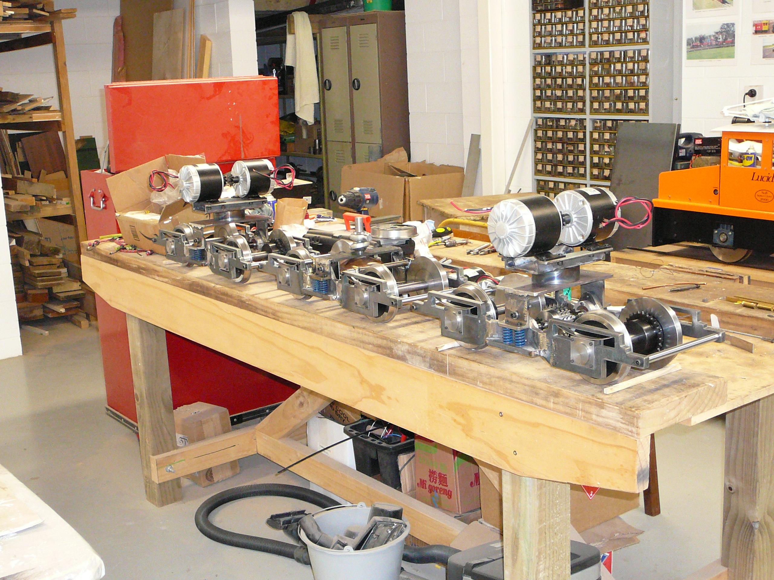
It was not long before the pieces came together to make up the three bogies. The centre articulated bogie is not powered but has a vacuum brake fitted for engine braking.
The two sections are articulated over the centre bogie by the use of ball joints.
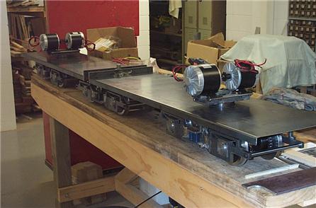
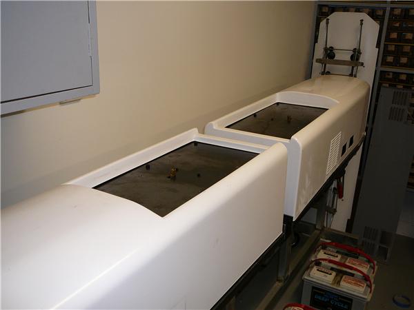
The platform sections were pressed from 2mm steel sheet folded along the edges. This formed a fairly rigid base to attach the other components. Even at this stage it is easy to see how the motors will be mounted above the platforms.
The pantographs are mounted on supporting stands over which the body sections will fit. Sitting on the platform in front of the stand supports is the actuating mechanism which has been created using a vacuum.
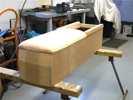
I decided to make the body shells from fibreglass due to the compound curves on the front. This meant making a pattern from custom wood first.This shows it under construction From the pattern a mould was made and from the mould two identical body sections were moulded..
The final result was very pleasing. Ventilator holes were cut and suitable louvre mouldings found with grills for the sides. The windows were cut out and roof top ventilator shrouds were cast and fitted.
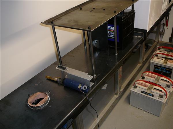
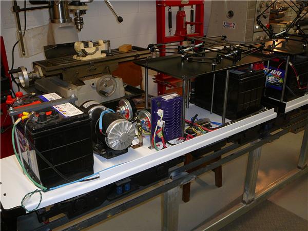
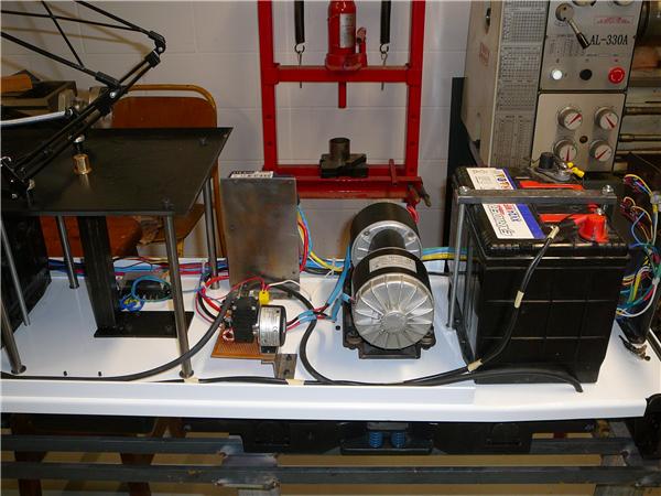
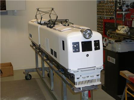
Fitting of the various components that make up the heart of the locomotive progressed well. This picture is of the front section which housed the horns front drive controller, engine braking solenoid and the two front batteries.
The rear section houses the rear section controller, rear batteries, vacuum pump and train brake solenoid. At the rear of this section is the control panel and hand control socket.
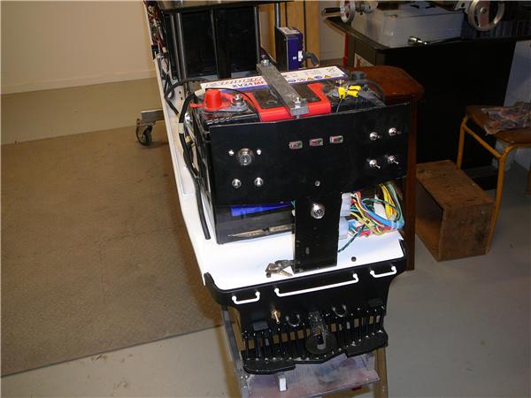
The control panel at the rear of the locomotive on the left side has the key switch to each side is a controller status light. Below the key switch are sited the front and rear light switches. The centre of the panel has three indicator meters, 2 for front and rear motor current and 1 for battery voltage. It will also have the speedometer head. To the right are located on the upper two switches the vacuum pump switch and reversing switch. Under these are the front and rear pantograph raising and lowering switches. In the centre is the hand control socket
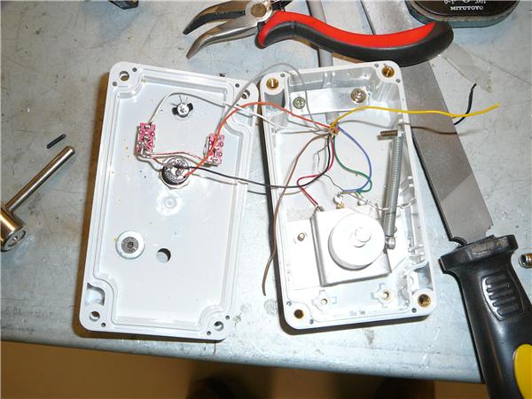
The control of the locomotive is via an umbilical chord to the hand control which houses the speed control, braking switches and horn. Here it is seen partly wired. Note the spring loading of the speed control to return it to zero automatically.
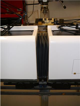
Between the two sections a set of bellows functions. These cover the ball joints and the 14 pin plug connecting the two sections together. The bellows slide into channels on the back panels and can be easily removed for access. As the whole locomotive is in excess of 2.4 metres it has to be split for transporting. A jockey wheel set is situated between the rear section vacuum tanks. It is lowered in the same way as a trailer jockey wheel and lifts the swivel joints apart to release the rear section from the front.
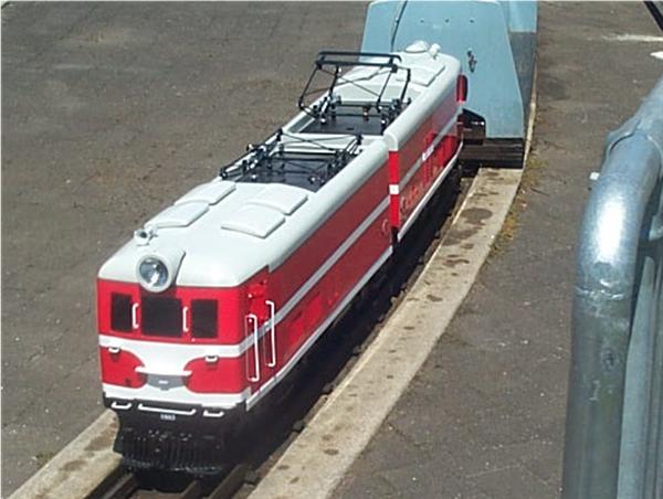
With the painting now completed, the handrails ventilators and rear view mirrors have been attached. The windows have been put in and the EW is ready for it's first test run on the track .